


Instant E-Stop Visibility — Without Rewiring or PLC Changes
The retrofit smart E-Stop indicator system
A patent-pending clip-on sensor module and indicator panel that retrofit onto any existing Emergency Stop. Instantly see which E-Stop has been pressed — wireless or USB-C operation, designed for industry, SMEs, and education

How It Works
A retrofit system designed to work with any existing Emergency Stop. No rewiring, no PLC changes.
1. Clip-On Sensor Module
Attaches directly to existing E-Stops without altering wiring.
Uses a magnetic reed or Hall-effect sensor to detect activation.
Battery powered, with optional USB-C wired power/data mode.
2. Wireless or USB-C Communication
Long-range sub-GHz wireless for most workshops and production areas.
USB-C wired mode for RF-restricted environments.
3. Indicator Panel
Displays exactly which E-Stop has been pressed in real time.
Supports optional cloud analytics for history, reporting, and multi-site visibility.
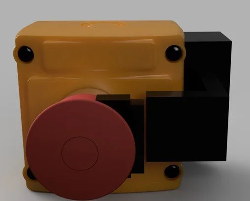
Concept Rendering — Clip-On Smart E-Stop Sensor Module
Shown attached to a standard industrial E-Stop housing. Final appearance subject to refinement.

Why It Matters
The Problem
Emergency Stops are pressed thousands of times per day across industry — but operators often have no visibility of which one was triggered.
This causes:
Unnecessary downtime
Slower response during incidents
Poor traceability and safety reporting
Increased training time
Compliance challenges for SMEs and education
Traditional “smart” systems cost £3,000–£10,000 per line and require rewiring or PLC integration.
The Solution
Close Safety Systems provides a simple, low-cost retrofit clip-on module that instantly identifies which E-Stop has been pressed — without touching the safety circuit.
No rewiring
No PLC changes
No installation downtime
Fits any existing E-Stop
Works in both wireless or RF-restricted environments
Why It’s Better
Costs a fraction of existing diagnostic systems
Fully retrofit — installs in minutes
Universal compatibility
Optional cloud analytics for history, reporting, and multi-site visibility
Designed for SMEs, training centres, education, and large industry


Product Features
🔧
Clip-On Smart Sensor Module
Attaches to any existing E-Stop without rewiring or modifying the safety circuit.
Uses magnetic reed or Hall-effect sensing for reliable activation detection.
Battery powered, with optional USB-C wired mode.
Key Features:
Zero rewiring required
Fits any industrial E-Stop
Secure clip-on mounting
Industrial-grade sensing
Replaceable battery
🔌📡
Wireless or USB-C Communication
Long-range sub-GHz wireless for workshops, training centres, and factories.
Optional USB-C wired mode for RF-restricted environments such as defence and aerospace.
Automatic fail-safe reporting ensures no signal is ever missed.
Key Features:
Up to 300m wireless range
Sub-GHz industrial frequency
Cross-wall penetration
USB-C power + data mode
Auto fail-safe reporting
📟
Real-Time Indicator Panel
Displays exactly which E-Stop has been pressed in real time.
Supports multi-stop monitoring and cloud analytics.
Fast, clear visibility for operators, instructors, and safety officers.
Key Features:
Supports multiple E-Stops
Bright 7-segment display
Audible alert option
Plug-and-play installation
Cloud logging optional
Specs at a Glance:
🔋 Battery life: 12–18 months | 📡 Range: 300m | ⚙️ Compatibility: Fits all E-Stops | 🔌 Power: USB-C / Battery

How It Compares

A Simple, retrofit-first solution that adds visibility traditional systems can’t provide
🛠️
Why Choose Close Safety Systems
Truly Retrofit-First
Industrial-Grade Wireless
Universally Compatible
Optional Cloud Analytics
Installs in minutes without rewiring or PLC changes.
Sub-GHz long-range connectivity built for factories and workshops.
Add reporting, alerting, and visibility across sites.
📡
🧩
☁️
Works with any existing E-Stop, any brand, any vintage.
Our Development Roadmap
A clear plan for delivering the full Close Safety Systems platform.
This roadmap outlines the technical, regulatory, and commercial milestones required to bring Close Safety Systems from prototype to a fully licensed and scalable product platform.
🔧 2026
Prototype Development & Pilot Preparation
✔ Q1
Finalise full functional spec
Select engineering partner
Begin radio technology testing (LoRa / sub-GHz)
CAD enclosure & PCB preliminary design
✔ Q2
Build proof-of-concept PCB
Begin firmware development
Early wireless range testing
Prepare pilot/demo materials
✔ Q3
Produce Version 1 prototypes
In-house controlled testing
Early compliance assessment
Recruit pilot sites (SMEs, education, workshops)
✔ Q4
Deploy prototypes to pilot sites
Gather real downtime/incident data
Refine hardware & firmware
Begin licensing discussions
🧩 2027
Production Engineering, Licensing & SaaS Beta
✔ Q1
Manufacture-ready Version 2 prototypes
Finalise enclosure + PCB
Expanded pilot deployments
✔ Q2
Manufacture-ready Version 2 prototypes
Finalise enclosure + PCB
Expanded pilot deployments
✔ Q3
Licensing negotiations with manufacturers
Draft royalty/licensing agreements
Closed SaaS beta launch with pilot users
✔ Q4
Licensing agreements confirmed
Deliver manufacturing package to partners
Prepare 2028 commercial rollout
🛡️ 2028
Commercial Rollout & Expansion
✔ Q1
Manufacturing & distribution by license partners
Public SaaS platform launch
Marketing campaign begins
✔ Q1
International licensing expansion
Grow SaaS dashboards & analytics
✔ Q3 - Q4
Expand partner network
Add hardware variants (range extender, low-cost variants)
Grow royalties + recurring SaaS revenue